Table of Contents
A Test Power Panel
We're going to build ourselves a “power test panel” for testing one or two motors at a time for workshop demonstrations and for mechanism prototyping. We've lashed this up a few times in the past, and its proved its usefulness. Now we'll do it in a tidier, more durable form.
I'm sure we can do it more neatly than the one pictured here: https://www.chiefdelphi.com/forums/showthread.php?t=152051 (never mind the text of that thread)
On the panel will be some basic robot electrical components:
- battery (with SB50 connectors)
- power distribution panel (an old FRC-2015 blue one)
- some motor controller
In addition, we're going to add a volt/amp meter to check battery condition and current drawn by things under test: Volt/Amp meter (Amazon)
In order to activate the motor controller, we'll need a souce of PWM data. Initially, we'll use this one that I built a few years back: PWM generator with display. Alternately, one could buy one or two of these: http://www.andymark.com/Thrifty-Throttle-p/am-2936a.htm Or we can build somthing using an arduino or other processor.
Wiring diagram
Here's how we'll wire the battery to the PDB. Note that we're inserting the measurement shunt for the ammeter into the negative lead. This wouldn't be FRC-legal on a competition robot, but is exactly what we want for our test board.

- Battery + to breaker (red)
- Breaker to PDB (red)
- Battery - to current shunt (black)
- shunt to PDB (black)
We wire the volt/amp meter unit exactly according to its documentation. Incorrect meter wiring could damage the meter or cause it to read improperly. There's a picture on the back of the meter unit.
Be sure to insulate all of these connections with electrical tape.
Finished test panel
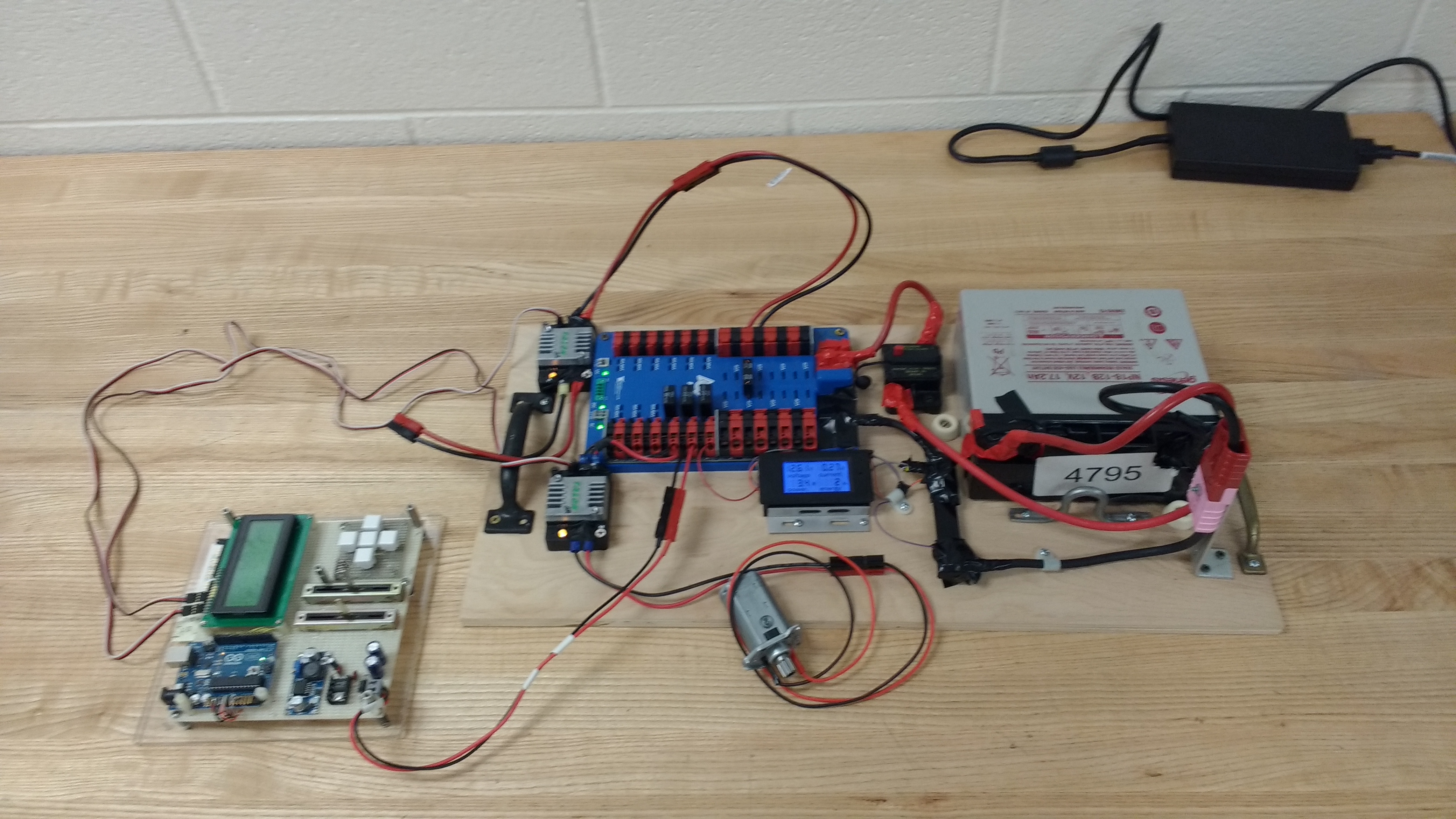
Closeup of the PDB and meter
