Table of Contents
LED's

2x Strips of RGB Addressable LED's
The silicone protective layer started to flake off, however didn't affect the performance of the LED's
Github
LED.java
Cool Wave!
 public void wave(HSVPreset color, double time) {
    for (var i = 0; i < buffer.getLength(); i++) {
      double v = 140 + Math.sin((i - pixelOffset) / (double) buffer.getLength() * Math.PI * 2) * 115;
      buffer.setHSV(i, color.h, color.v, (int) v);
    }

    if (timer.get() < time) {
      if (pixelOffset == buffer.getLength() - 1) {
        pixelOffset = 0;
      }
    } else {
      pixelOffset += 1;
      timer.reset();
    }

    led.setData(buffer);
    led.start();
  }
LED States
Purple Top-Bottom Animation: Indicates the shooter RPM's, solid purple when up to speed
Purple Wave Animation: Indicates that the climber is active and is moving up or down
Solid Alliance Color: The default state of the LED's, no balls detected and no climbing
Half Green: Indicates that a ball is in the top position of the tower
Full Green: Indicates that two balls are in their positions in the tower
LED Wiring
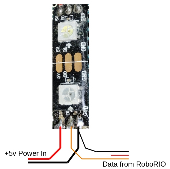
These LED strips have three wires:
- +5v Power
- Data stream (controls the colors)
- Ground - common return for data and power
The data stream comes from a RoboRIO PWM output, as described here https://docs.wpilib.org/en/stable/docs/software/hardware-apis/misc/addressable-leds.html
RIO PWM outputs have power, but is not the right power: PWMs have 6 volt power, intended for servo motors. It might not kill the LEDs immediately, but might reduce their lifetime a lot. And the RoboRIO can't supply enough current for a long string of LEDs anyway.
So, we need to split the wiring. Power comes in on two wires, red for power and black for ground. and we use a seperate scrap of a PWM cable for data. The center red wire of the PWM cable is not used, only black (ground) and white (data).
Here's a sketch of which wires go where:
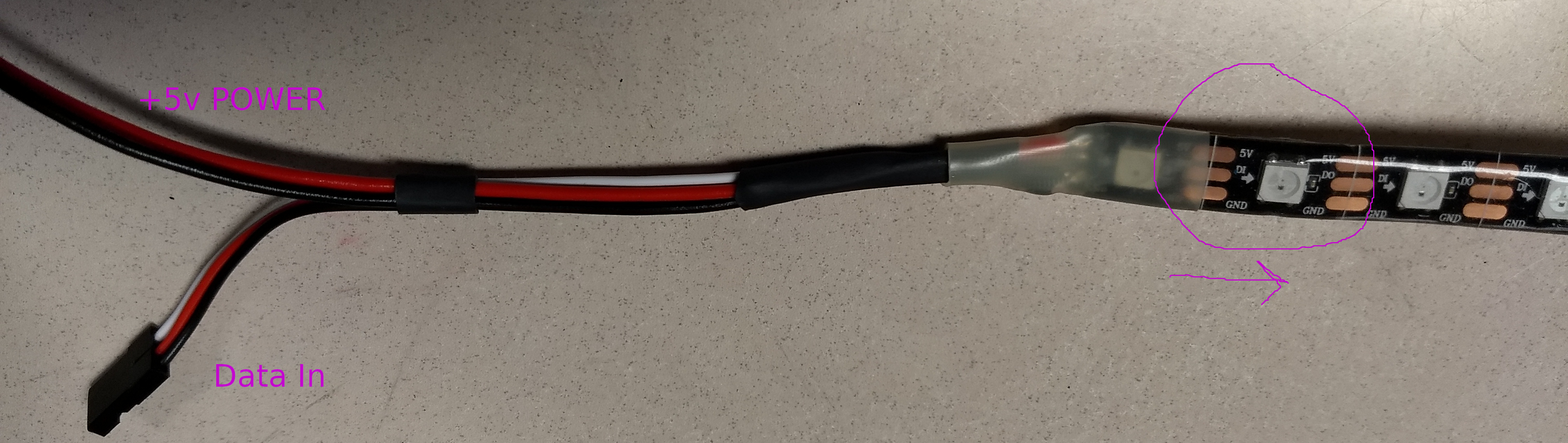
and here's a picture of one assembled:
Mutiple strips of LEDs
There are at least two ways to do multiple strips of LEDs:
1. chain them together. solder to the data-out pin of the first strip, and wire that to the data-in pin of another strip. Every 20 LEDs or so, connect another +5v wire directly to the 5v power supply.
2. Wire them in parallel, feeding the same data to both strips. This is what we did. The two strips are on different sides of the robot, so it the status can be seen from both sides. Wiring them together makes the two sides always look the same, without any special software.
We used a PWM Y-adaptor to connect both strips to the same RoboRIO PWM output.
Where does the +5v power come from
We used the +5v output of a VRM. Its good for 2 amps, which is enough for about 1 meter of a typical 60-LED-per-meter strip. If we needed more LEDs, we'd have to use a different 12v to 5v “buck” converter.
LED Test Board
We had a short piece of LED strip left over, so we built a little test board. With only two LEDs, the 5v power can come from a RoboRIO DIO terminal. So this board can plug directly into a RoboRIO for software testing.
