Table of Contents
When using I2C sensors, we almost always have to run a cable from the RoboRIO to the sensor itself. Sometimes there's a problem with the wiring. This page has some techniques for testing and troubleshooting i2c wiring.
The RoboRIO i2c connector looks like this:

It has four pins:
- common or ground
- 3.3v power or running the sensor
- SCL, “serial clock”
- SDA, “serial data”
Grab the multimeter
To see if the i2c port is alive, and getting properly conveyed to the other end of a cable, one can grab a multimeter. If the cable can be removed and tested seperately, do that first using the “ohms” or “continuity” function. Be sure to check for shorts between wires as well as continuity of each wire from end to end. Also be sure to visually inspect the cable, looking for damaged pins, or pins not fully inserted into the connector housing.
We can also test the far end of i2c cable, to see if we can “see” the RoboRIO through the cable.
- Set the digital multimeter to read DC voltage or “volts”
- connect the black (negative) meter lead to the ground pin of the i2c cable
- Touch the red (positive) meter lead to the “3.3v” terminal. Expect to see about 3.3 volts, plus or minus a tenth of a volt or so.
- Then, touch the red lead to SCL. Expect to read about 3.3v here also.
- Repeat for SDA. We also expect to read 3.3v here.
Why 3.3v on the SCL and SDA data pins? The RoboRIO has a pullup resistor on each of those pins which weakly connect them to the 3.3v supply when they are not otherwise pulled low. If we can see that voltage, the wire is likely connected.
One thing this test doesn't do is identify if SDA and SCL are swapped, or shorted together. That's a bit harder. But checking cable continuity to confirm that the cable is built properly should take care of most cases.
Can we do somthing better/faster?
I2C Cable Test Tool
Here's an idea for a simple wiring test tool that will show if somthing like the correct voltages are present on the I2C pins.
How it works
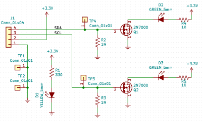
First, there's a basic LED circuit (TODO link) that indicates if there's power.
On each of SCL and SDA signals, a 2n7000 MOSFET transistor detects if the voltage on the wire is pulled high (to near 3 or 5 volts) by a pull-up resistor. This indicates that at least the wire is connected to *somthing*. When the signal is high, the transistor turns ON, completing a circuit to light the associated LED. A very large resistor, 1 Meg ohms (1 x 10**9 ohms) pulls each signal to zero volts if it isn't connected at all, but doesn't disturb normal operation.
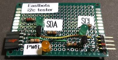
First prototype:


